Setup WireGuard Site to Site VPN Tunnel on pfsense 2.7.2
This guide was inspired by Marcus Rath
Introduction
This guide will walk you through setting up a WireGuard site to site VPN tunnel on pfsense 2.7.2. For this guide we assume Site A with a network subnet of 192.168.1.0/24, Site B with a network subnet of 192.168.24.0/24 and a Tunnel Subnet of 10.10.12.0/30. Obviously adjust these settings to your specific needs.
Ensure that the Tunnel Subnet you choose does NOT overlap with any other network subnets currently in use in your network environment.
Install WireGuard Package on Both Sites
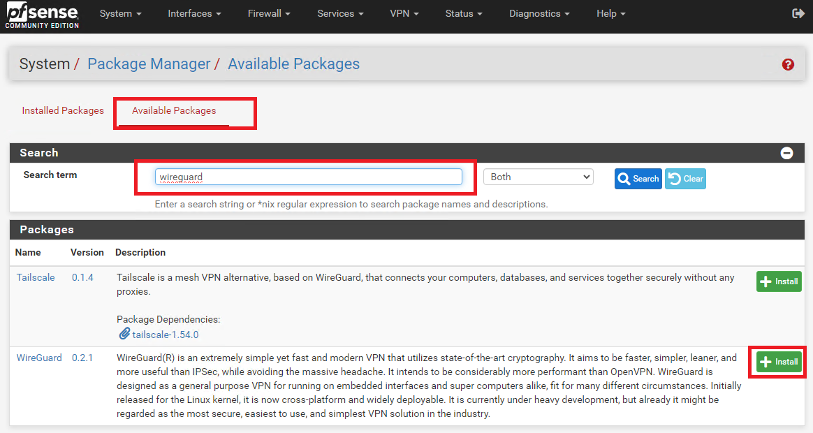
On BOTH site pfsense installations, install the WireGuard package from System ---> Package Manager ---> Available Packages. Enter Wireguard in the Search term field, click search and then click on the Install button next to WireGuard package (Figure 1).
Figure 1
Create Tunnel on Site A
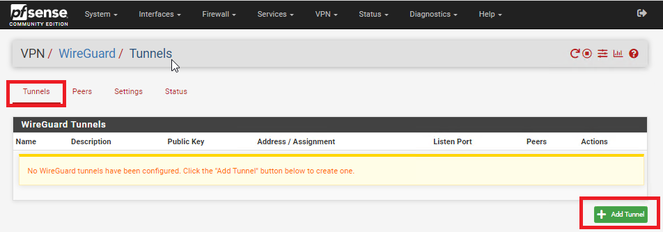
On Site A, refresh the pfsense web GUI and navigate to VPN ---> Wireguard, click on the Tunnels tab and then click on Add Tunnel button (Figure 2).
Figure 2
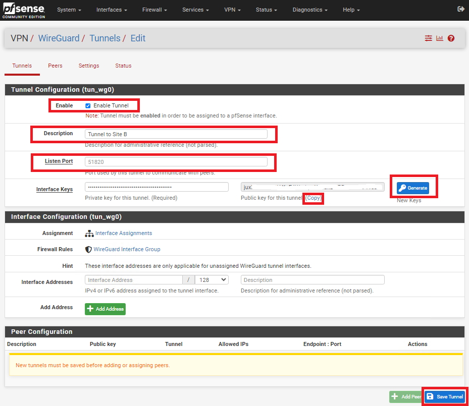
In the Tunnel Configuration fill/set in the following fields (Figure 3):
- Enable: Checked
- Description: Optionally, describe the purpose of this tunnel (Ex: Tunnel to Site B)
- Listen Port: Leave blank to use port UDP/51820 or enter a specific port number you with to use
- Interface Keys: click the Generate button to create a new Private/Public key pair and copy the Public Key that's generated in order to enter it in the Public Key field on Site B.
- Click the Save Tunnel button
Figure 3
Create Tunnel on Site B
On Site B, refresh the pfsense web GUI and navigate to VPN ---> Wireguard, click on the Tunnels tab and then click on Add Tunnel button (Figure 4).
Figure 4
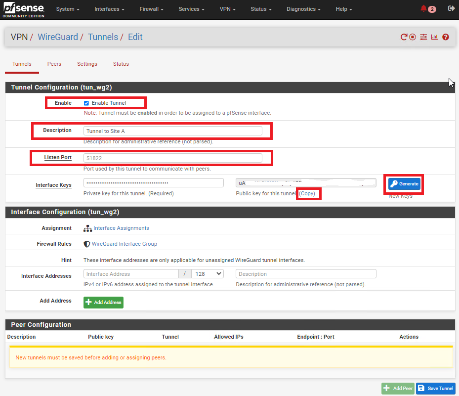
In the Tunnel Configuration fill/set in the following fields (Figure 5):
- Enable: Checked
- Description: Optionally, describe the purpose of this tunnel(Ex: Tunnel to Site A)
- Listen Port: Leave blank to use port UDP/51820 or enter a specific port number you with to use
- Interface Keys: click the Generate button to create a new Private/Public key pair and copy the Public Key that's generated in order to enter it in the Public Key field on Site B.
- Click the Save Tunnel button
Figure 5
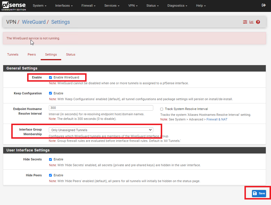
Enable WireGuard on Both Sites
Figure 6
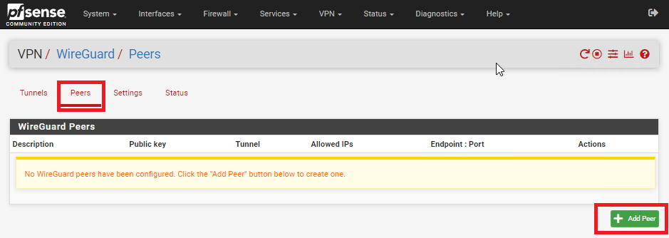
Add Peer on Site A
Figure 7
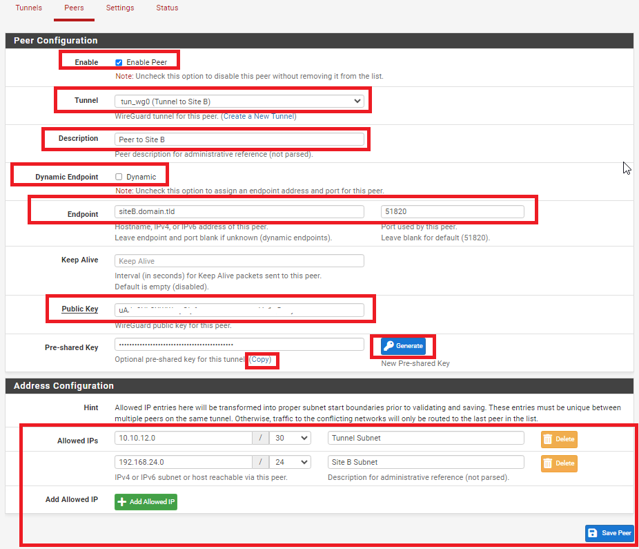
In the Peer Configuration fill/set in the following fields (Figure 8):
- Enable: Checked
- Tunnel: Select the Tunnel previously configured from the drop-down list
- Description: Optionally, describe the purpose of this Peer (Ex: Peer to Site B)
- Dynamic Endpoint: Unchecked
- Endpoint: Fill in the Internet IP or Hostname as well as the port number for Site B
- Public Key: Paste the previously copied Public Key from the Tunnel on Site B
- Pre-shared Key: Click the Generate button to generate a new pre-shared key and copy it in order to paste in the Peer configuration of Site B
- Allowed IPs: Enter an UNUSED Network address (Example: 10.10.12.0) with a CIDR of 30 (For a total of two IPs) in the first field, click the Add Allowed IP and then enter the Network Address and corresponding CIDR of the subnet for Site B
- Click the Save Peer button
Figure 8
Add Peer on Site B
Figure 9
In the Peer Configuration fill/set in the following fields (Figure 10):
- Enable: Checked
- Tunnel: Select the Tunnel previously configured from the drop-down list
- Description: Optionally, describe the purpose of this Peer (Ex: Peer to Site A)
- Dynamic Endpoint: Unchecked
- Endpoint: Fill in the Internet IP or Hostname as well as the port number for Site A
- Public Key: Paste the previously copied Public Key from the Tunnel on Site A
- Pre-shared Key: Paste the previously copied Pre-Shared key from the Peer on Site A
- Allowed IPs: Enter the SAME Tunnel Subnet Network address and CIDR you set on the Peer on Site A, click the Add Allowed IP and then enter the Network Address and corresponding CIDR of the subnet for Site A
- Click the Save Peer button
Figure 10
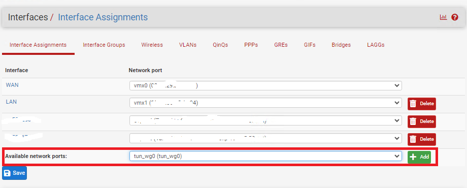
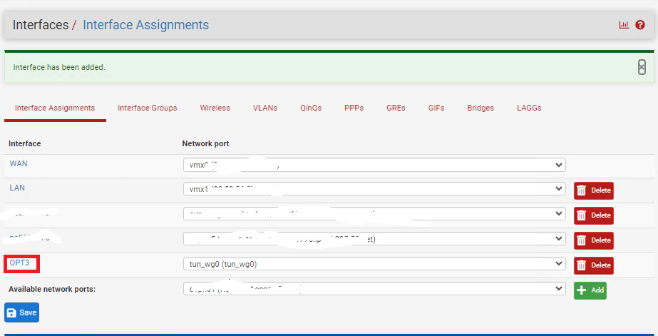
Configure Interface for Site A
Figure 11
Click on the new OPT(X) interface that was just created (Figure 12).
Figure 12
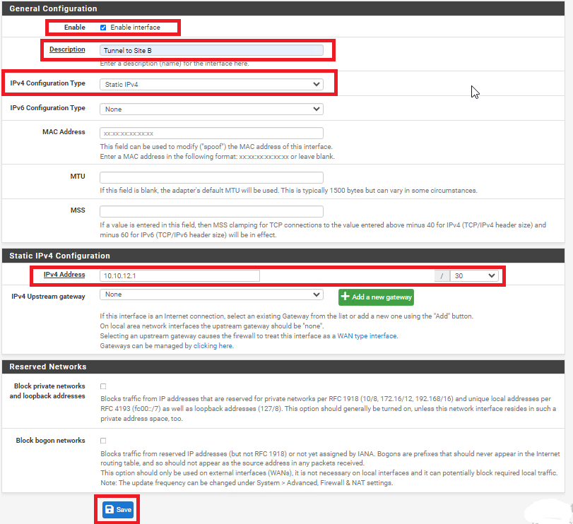
In the General Configuration page fill/set the following fields (Figure 13):
- Enable: Checked
- Description: Optionally, describe the purpose of this Interface (Ex: Tunnel to Site B)
- IPv4 Configuration Type: Static IPv4
- IPv4 Address: Enter an IP address for Site A. The IP address you enter here will be one of two possible IP addresses you can use from the /30 Tunnel Subnet you chose earlier. For this example, we used the Subnet Tunnel of 10.10.12.0/30 which gives us 10.10.12.1 and 10.10.12.2 as the only two usable IPs for this subnet. So, for this example we will use 10.10.12.1 for Site A.
- Click the Save button and then click the Apply Changes button.
Figure 13
Configure Interface for Site B
Figure 14
Click on the new OPT(X) interface that was just created (Figure 15).
Figure 15
In the General Configuration page fill/set the following fields (Figure 16):
- Enable: Checked
- Description: Optionally, describe the purpose of this Interface (Ex: Tunnel to Site A)
- IPv4 Configuration Type: Static IPv4
- IPv4 Address: Enter an IP address for Site B. The IP address you enter here will be one of two possible IP addresses you can use from the /30 Tunnel Subnet you chose earlier. For this example, we used the Subnet Tunnel of 10.10.12.0/30 which gives us 10.10.12.1 and 10.10.12.2 as the only two usable IPs for this subnet. So, for this example we will use 10.10.12.2 for Site B.
- Click the Save button and then click the Apply Changes button.
Figure 16

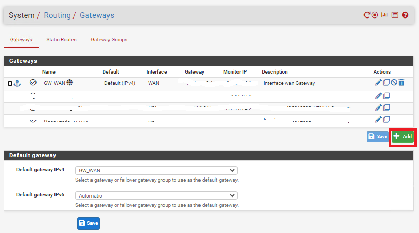
Create Gateway and Route on Site A
Figure 17
In the Edit Gateway page fill/set the following fields (Figure 18):
- Disabled: Unchecked
- Interface: Select the interface for Site A you created earlier
- Name: Enter a name for this gateway (Ex: WG_GW_Site_B)
- Gateway: Enter the Tunnel Subnet IP address for Site B. For this example we used 10.10.12.2 for Site B.
- Description: Optionally, enter a description (Ex: Wireguard Gateway to Site B)
- Click the Save button and then click the Apply Changes button.
Figure 18
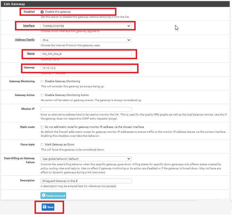
Figure 19
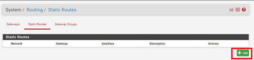
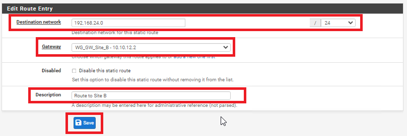
In the Edit Route Entry page, fill/set the following fields (Figure 20):
- Destination network: Enter the network subnet for Site B (NOT the tunnel subnet). In this example, the network subnet we used for Site B was 192.168.24.0/24.
- Gateway: Select the Gateway to Site B you created earlier
- Description: Optionally, enter a description (Ex: Route to Site B)
- Click the Save button and then click the Apply Changes button.
Figure 20
Create Gateway and Route on Site B
Figure 21
In the Edit Gateway page fill/set the following fields (Figure 22):
- Disabled: Unchecked
- Interface: Select the interface for Site A you created earlier
- Name: Enter a name for this gateway (Ex: WG_GW_Site_A)
- Gateway: Enter the Tunnel Subnet IP address for Site A. For this example we used 10.10.12.1 for Site A.
- Description: Optionally, enter a description (Ex: Wireguard Gateway to Site A)
- Click the Save button and then click the Apply Changes button.
Figure 22
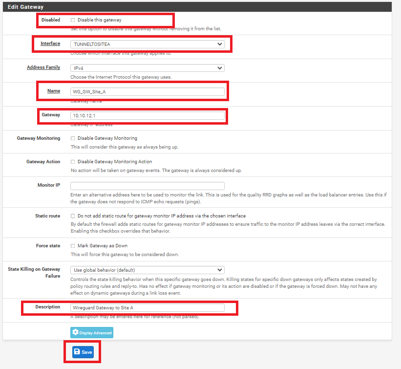
Figure 23
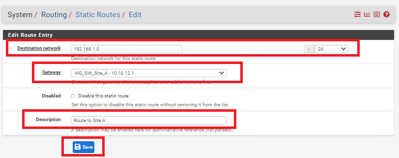
In the Edit Route Entry page, fill/set the following fields (Figure 24):
- Destination network: Enter the network subnet for Site A (NOT the tunnel subnet). In this example, the network subnet we used for Site A was 192.168.1.0/24.
- Gateway: Select the Gateway to Site A you created earlier
- Description: Optionally, enter a description (Ex: Route to Site A)
- Click the Save button and then click the Apply Changes button.
Figure 24
Add Firewall Rules on BOTH Firewalls
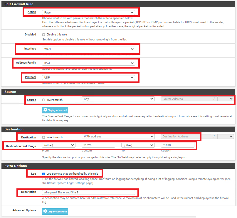
On BOTH firewalls, navigate to Firewall ---> Rules and under the WAN tab, click the Add button. In the Edit Firewall Rule page, fill/set the following fields (Figure 25).
- Action: Pass
- Interface: WAN
- Address Family: IPv4
- Protocol: UDP
- Source: Any
- Destination: WAN address
- Destination Port Range: (other) 51820 to (other) 51820
- Log: Optionally, check to Log packets that are handled by this rule
- Description: Optionally, enter a description (Ex: Wireguard Site A and Site B)
- Click the Save button and then click the Apply Changes button.
Figure 25
On BOTH firewalls, navigate to Firewall ---> Rules and under the TUNNELTOSITE(X) tab, click the Add button. In the Edit Firewall Rule page, fill/set the following fields (Figure 25).
- Action: Pass
- Interface: Ensure the interface you created earlier for each site is already selected
- Address Family: IPv4
- Protocol: Any (Start with Any and then you can tighten the rules further after you ensure tunnel is working properly)
- Source: Any (Start with Any and then you can tighten the rules further after you ensure tunnel is working properly)
- Destination: Any (Start with Any and then you can tighten the rules further after you ensure tunnel is working properly)
- Destination Port Range: Any (Start with Any and then you can tighten the rules further after you ensure tunnel is working properly)
- Log: Optionally, check to Log packets that are handled by this rule
- Description: Optionally, enter a description (Ex: Wireguard Traffic Site A and Site B)
- Click the Save button and then click the Apply Changes button.
Figure 25
Check the Wireguard Status
On BOTH firewalls navigate to Status ---> Wireguard, locate the WireGuard tunnel you created, expand it and ensure the Peers are connected on BOTH firewalls (Figure 26).
Figure 26
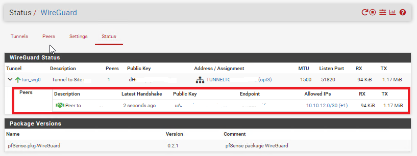
Additionally, ensure you can ping and access resources on each remote network from the corresponding site.