pfsense
- pfsense 2.4 with Always-On Load Balanced OpenVPN Connections
- PfSense, HAProxy, SoftEther VPN
- Setup WireGuard Site to Site VPN Tunnel on pfsense 2.7.2
pfsense 2.4 with Always-On Load Balanced OpenVPN Connections
Following this guide will allow you to create always-on load-balanced OpenVPN connections to your favorite VPN provider and force all your Internet traffic through the OpenVPN connections.
This guide was developed using Newshosting VPN account. The information contained will probably work with most other VPN providers with little or no modifications.
This guide is written for the privacy conscious who do not want their activities monitored by their ISP or other entities since the OpenVPN traffic is encrypted.
This guide is NOT written in order to assist you in conducting nefarious activities on the Internet undetected. A simple VPN connection is not enough to completely hide your digital tracks. Be warned!!
Import VPN Provider CA Certificate
- Obtain the CA Certificate from the VPN Provider.
- Navigate to System --> Cert. Manager.
- Click the Add button.
- Under the Descriptive name field, enter a description for the CA certificate your are importing.
- Under the Certificate data, paste the certificate contents including the -----BEGIN CERTIFICATE----- and the -----END CERTIFICATE----- parts.
- Click the Save button (Figure 1).
Figure 1
.jpg)
Create OpenVPN client connections
Figure 2
.jpg)
- In the Username field, enter the username for your VPN Provider.
- In the Password field, enter the password for your VPN Provider.
- Ensure the Use a TLS Key field is unchecked.
- In the Peer Certificate Authority field, ensure you select the CA that you created in the import VPN Provider CA Certificate section above.
- In the Client Certificate field, ensure that None (Username and/or Password required) is selected. Please note that this field may need to be adjusted to your VPN provider's requirements, however most of the VPN providers I've used, Username/Password has been sufficient.
- In the Encryption Algorithm field, select the highest encryption that your VPN provider supports. I've used AES-256-CBC (256 bit key, 128 bit block) with no problems (Figure 3).
Figure 3
.jpg)
- Ensure the Enable NCP field is unchecked.
- In the Auth digest algorithm field, select the auth digest algorithm supported by your VPN provider. I've used SHA256 (256-bit) with no problems.
- In the Hardware Crypto field, ensure No Hardware Crypto Acceleration is selected (Figure 4).
Figure 4
.jpg)
- In the Compression field, ensure that Adaptive LZO Compression [Legacy style, comp-lzo adaptive] is selected.
- Ensure Don't add or remove routes field is checked.
- In the Custom options field, paste the following options (Figure 5):
persist-key;
persist-tun;
persist-remote-ip;
resolv-retry infinite;
Figure 5
.jpg)
- Click the Save button.
- Create additional OpenVPN client connections as needed.
Verify OpenVPN Client Connections are Up
Figure 6
.jpg)
Assign Interfaces to each OpenVPN Connection
Figure 7
.jpg)
- Assign all the OpenVPN connections you created and you will end up with your OpenVPN connections having been assigned an OPTX interface name where X is a number assigned by the system. Ensure you click the Save button at the bottom of the screen to save your changes. (Figure 8).
Figure 8
.jpg)
- Next, click on each of the OPTX interfaces that were assigned to your OpenVPN connections and you will be re-directed to the Interfaces / OPTX configuration page where X is the interface number assigned by the system.
- Ensure the Enable field is checked.
- In the Description field enter a name for this connection (Ex: NewsHostingOpenVPN1).
- Ensure IPv4 Configuration Type is set to None.
- Ensure IPv6 Configuration Type is set to None (Figure 9).
Figure 9
.jpg)
- Click the Save button at the bottom of the page and then click the Apply Changes that appears on the top of the page after clicking the Save button.
- Navigate back to Interfaces --> Assignments and repeat Steps 9 through 14 from above to assign the rest of the OpenVPN connections.
- In the end you should end up with a listing like below under Interfaces -->Assignments (Figure 10).
Figure 10
.jpg)
Create OpenVPN Gateway Group
In this section, we are going to be creating a Gateway Group that's going to include all the OpenVPN gateways that were automatcially created by the system when we assigned the OpenVPN connections to Interfaces in the previous section. Using this method, we willl be having more than one connection available for load balancing as well as failover in case one of the OpenVPN connections goes down. You will notice below that we will give both OpenVPN gateways the same priority (Tier 1) which will effectively create a load-balanced connection using multiple OpenVPN gateways.
Figure 11
.jpg)
- Next, click on the Gateway Groups tab and then click the Add button (Figure 12).
Figure 12
.jpg)
- You will be re-directed to the Edit Gateway Group Entry page
- In the Group Name field, enter a name for your Gateway Group (Ex: OpenVPNGatewayGroup).
- Under the Gateway Priority section, ensure your main WAN gateway is set to Never.
- Ensure all the OpenVPN IPv4 gateways denoted with a _VPNV4 suffix are set to Tier 1. Ensure that any OpenVPN IPv6 gateways denoted with a _VPNV6 suffix are NOT set to Tier 1 and if necessary be set to Never just like the main WAN gateway.
- Ensure the Trigger Level field is set to Member down
- Optionally, enter a description in the Description field.
- Click the Save button (Figure 13).
Figure 13
.jpg)
- You will be re-directed back to Gateway Groups page where the you will be able to see the Gateway Group you just created. Click on the Apply Changes button on the top of the page to apply your changes (Figure 14).
Figure 14
.jpg)
Create Firewall Rules
In this section, we are going to create a floating firewall rule to Reject any LAN outbound packets that are tagged as NO_WAN_OUTBOUND and then we are going to create a LAN rule that will tag all traffic as NO_WAN_OUTBOUND as well as use the OpenVPNGatewayGroup we created in the section above as the default gateway for that traffic. Using this method, we are going to ensure that ALL LAN traffic will ONLY go through the OpenVPN connections.
Figure 15
.jpg)
Figure 16
![]()
- You will be re-directed to the Edit firewall Rule page.
- In the Action field ensure Reject is selected.
- In the Interface field ensure the WAN interface is selected.
- In the Direction field ensure out is selected.
- In the Address Family ensure IPv4 is selected.
- In the Protocol field ensure Any is selected(Figure 17).
Figure 17
.jpg)
- In the Log field, check the Log packets that are handled by this rule.
- In the Description field, enter the following description: Reject Packets tagged with NO_WAN_OUTBOUND.
- In the Advanced Options field, click Display Advanced button (Figure 18).
Figure 18
.jpg)
- Clicking the Advanced Options button from the previous step, will display the Advanced Options section.
- In the Tagged field, enter the following: NO_WAN_OUTBOUND (Figure 19). Ensure you make a note of the NO_WAN_OUTBOUND tag because we are going to be using it in LAN rule we are going to be creating next.
Figure 19
.jpg)
- Click the Save button at the bottom of the page.
- You will be re-directed back to the Floating rules tab page.
- Click on the Apply Changes button on the top of the page to apply the changes (Figure 20).
Figure 20
.jpg)
- Next click on the LAN tab (Figure 21).
Figure 21
.jpg)
Figure 22
![]()
- You will be re-directed to the Edit firewall Rule page.
- In the Action field ensure Pass is selected.
- In the Disabled field ensure Disable this rule is Unchecked.
- In the Interface field ensure the LAN interface is selected.
- In the Address Family ensure IPv4 is selected.
- In the Protocol field ensure Any is selected (Figure 23).
Figure 23
.jpg)
- Under the Source section, in the Source field, ensure LAN net is selected.
- Under the Destination section, in the Destination field, ensure any is selected.
- Under the Extra Options section, in the Log field, ensure Log packets that are handled by this rule is checked.
- Under the Extra Options section, in the Description field, enter a description for this rule (Ex: Allow LAN to any via VPN Only).
- Under the Extra Options section, in the Advanced Options field, click the Display Advanced button (Figure 24).
Figure 24
.jpg)
- Clicking the Advanced Options button from the previous step, will display the Advanced Options section.
- Under the Advanced Options section, in the Tag field, enter NO_WAN_OUTBOUND (Figure 25).
Figure 25
.jpg)
- Under the Advanced Options section, in the Gateway field, ensure the OpenVPNGatewayGroup gateway is selected (Figure 26).
Figure 26
.jpg)
- Click the Save button at the bottom of the page.
- You will be re-directed back to the LAN rules tab page.
- Click on the Apply Changes button on the top of the page to apply the changes (Figure 27).
Figure 27
.jpg)
Create a Rule to Bypass OpenVPN Connections
If you have a need for certain IPs inside your LAN to bypass the OpenVPN connections and go through the WAN gateway like normally, you would simply create a LAN rule and place it ABOVE the Allow LAN to any via VPN Only rule we created above.
Figure 28
.jpg)
Figure 29
.jpg)
- Under the Host(s) section, enter any LAN IPs (one per line) that you want to bypass the OpenVPN connections (You can add more lines by clicking the Add Host button at the bottom of the page).
- When finished, click the Save button at the bottom of the page (Figure 30).
Figure 30
.jpg)
- You will be re-directed back to the Aliases IP tab page.
- Click on the Apply Changes button on the top of the page to apply the changes (Figure 31).
Figure 31
.jpg)
Figure 32
.jpg)
Figure 33
![]()
- You will be re-directed to the Edit firewall Rule page.
- In the Action field ensure Pass is selected.
- In the Disabled field ensure Disable this rule is Unchecked.
- In the Interface field ensure the LAN interface is selected.
- In the Address Family ensure IPv4 is selected.
- In the Protocol field ensure Any is selected.
- Uder the Source section, in the Source field, ensure Single host or alias is selected and then enter the name of the alias you created above (Outbound_Direct_NO_VPN).
- Under the Destination section, in the Destination field, ensure any is selected (Figure 34).
Figure 34

- Under the Extra Options section, in the Log field, ensure Log packets that are handled by this rule is checked.
- Under the Extra Options section, in the Description field, enter a description for this rule (Ex: Allow LAN to any rule NO VPN) (Figure 35).
Figure 35

- Click the Save button at the bottom of the page.
- You will be re-directed back to the LAN rules tab page.
- Click on the Apply Changes button on the top of the page to apply the changes (Figure 36).
Figure 36
PfSense, HAProxy, SoftEther VPN
Introduction
This guide was written in order to assist in setting up HAProxy in PfSense in order to route SSL (443) traffic to either a SoftEther SSL VPN server or a webserver listening on port 443 based on SNI. In actuality, any SSL VPN server will suffice, however SoftEther VPN is the server of choice in this example.
Software Used
- PfSense Version 2.4.4
- HAProxy Version 17-1.7.11_1 for PfSense
Install HAProxy in Pfsense
- In the PfSense Web GUI, click on System --> Package Manager --> Available Packages.
- Locate the haproxy package, click on the Install button and wait for the installation to complete.
- After haproxy succesfully installs, click on Services --> HAProxy --> Backend
Add SoftEther VPN Backend
- In the Backend tab, click the Add button.
- In the Edit HAProxy Backend server pool page set the following:
- In the Name field, enter a name Ex: SoftEtherVPN.
- In the Server list section, click the down arror icon
 to add a new server entry.
 - In the Mode field ensure active is selected
- In the Name field enter a name Ex: SoftEtherVPN
- In the Forwardto field ensure Address+Port is selected
- In the Address field enter the IP address of your SoftEther VPN Server Ex: 192.168.0.100
- In the Port field enter 443
- Ensure Encrypt(SSL) is unchecked
- Ensure SSL checks is unchecked
- Ensure Weight is empty
- Scroll down to the Health checking section and ensure None is selected in the Health check method field
- Click the Save button at the bottom of the page (Figure 1)
Figure 1
.png)
Add Webserver Backend
- Back the Backend tab, click the Add button.
- In the Edit HAProxy Backend server pool page set the following:
- In the Name field, enter a name Ex: Webserver.
- In the Server list section, click the down arrow icon to add a new server entry.
- In the Mode field ensure active is selected
- In the Name field enter a name Ex: Webserver
- In the Forwardto field ensure Address+Port is selected
- In the Address field enter the IP address of your SoftEther VPN Server Ex: 192.168.0.200
- In the Port field enter 443
- Ensure Encrypt(SSL) is unchecked
- Ensure SSL checks is unchecked
- Ensure Weight is empty
- Scroll down to the Health checking section and ensure None is selected in the Health check method field
- Click the Save button at the bottom of the page (Figure 2)
Figure 2
.png)
- Back in the Backend tab, click on the Apply Changes button (Figure 3)
Figure 3
.png)
Add Frontend
- Click on Services --> HAProxy --> Frontend
- Click the Add button
- In the Edit HAProxy Frontend page set the following:
- In the Name field enter a friendlyname Ex: widgetsinc-frontend
- Ensure the Status field is set to Active
- Under the External Address --> Table section, ensure the Listen Address field is set to WAN address (IPv4)
- Ensure the Type field is set to ssl /https(TCP mode)
- Under the External Address --> Table section, ensure the Port field is set to 443
- Under the External Address --> Table section, ensure the SSL Offloading field is unchecked
- Under the External Address --> Table section, ensure the Advanced field is empty
- Under the Type section, ensure ssl/https(TCP mode) is selected
- Under the Default backend, access control lists and actions --> Access Control lists section, click the down arrow icon to add an ACL entry for the SoftEther VPN Server
- In the Name field enter a name for this ACL Ex: SoftetherACL
- In the Expression field ensure Server Name Indication TLS extension matches is selected
- Ensure the CS field is unchecked
- Ensure the Not field is unchecked
- In the Value field, enter the FQDN to reach your SoftEther VPN server Ex: vpn.domain.tld
- Again, click the down arrow icon to add an ACL entry for the Webserver
- In the Name field enter a name for this ACL Ex: WebserverACL
- In the Expression field ensure Server Name Indication TLS extension matches is selected
- Ensure the CS field is unchecked
- Ensure the Not field is unchecked
- In the Value field, enter the FQDN to reach your Webserver Ex: www.domain.tld
- Under the Default backend, access control lists and actions --> Actions section, click the down arrow icon to add an action for the SoftEther VPN ACL we created above
- In the Action field, ensure Use Backend is selected and ensure the SoftetherVPN backend we created earlier is selected
- In the Condition acl names field, enter the ACL name you set for the Softether ACL Ex: SoftetherACL
- Again, click the down arrow icon to add an action for the Webserver ACL we created above
- In the Action field, ensure Use Backend is selected and ensure the Webserver backend we created earlier is selected
- In the Condition acl names field, enter the ACL name you set for the Webserver ACL Ex: WebserverACL (Figure 4)
Figure 4
.png)
Enable HAProxy
- Click on Services --> HAProxy --> Settings
- Under General Settings --> Enable HAProxy field is checked
- In the General Settings --> Maximum Connections field, enter the number of connections per process Ex: 1000
- Click the Save button on the bottom of the page (Figure 5)
Figure 5
.png)
- Back in the Settings tab, click on the Apply Changes button (Figure 6)
Figure 6
.png)
Add Firewall Rule
- Click on Firewall --> Rules
- Click the Add button
- n the Edit Firewall Rule page set the following:
- Ensure the Interface field is set to WAN
- Ensure the Address Family field is set to IPv4
- Ensure the Protocol field is set to TCP
- Under the Source section, ensure Source field is set to any
- Under the Destination section, ensure Destination is set to WAN address
- Under the Destination section, ensure Destination Port Range From is set to HTTPS (443) and To is set HTTPS (443)
- Under Extra Options section, set the Description field
- Click the Save button at the bottom of the page (Figure 7)
Figure 7
.png)
- Back in the Firewall/ Rules / Wan tab, click on the Apply Changes button (Figure 8)
Figure 8
.png)
Install Service Watchdog in PfSense
This setup has the potential to expose the PfSense Web GUI to the Internet if the HAProxy service ever fails. In order to mitigate this issue, it's a good idea to install the Service Watchdog package in PfSense so that it can monitor the HAProxy service and start it automatically if it ever fails. Alternatively, you can change the PfSense Web GUI to another port other than 443.
- In the PfSense Web GUI, click on System --> Package Manager --> Available Packages.
- Locate the Service_Watchdog package, click on the Install button and wait for the installation to complete.
- After Service_Watchdog succesfully installs, click on Services --> Service Watchdog
- Click on the Add New Service button
- In the Add Service to Monitor page, in the Service to Add field, select haproxy: TCP/HTTP(S) Load Balancer from the drop-down and click the Add button (Figure 9)
Figure 9

If you are NOT using HAProxy on PfSense
If you are trying to implement HAProxy standalone i.e. not part of PfSense, below is the configuration generated by the PfSense package. Hopefully it will assist someone in their own HAProxy implementation. Ensure you change widgetsinc-frontend, PUBLIC_IP_ADDRESS, vpn.domain.tld and www.domain.tld to fit your needs.
global
    maxconn            1000
    stats socket /tmp/haproxy.socket level admin
    uid            80
    gid            80
    nbproc            1
    hard-stop-after        15m
    chroot                /tmp/haproxy_chroot
    daemon
    server-state-file /tmp/haproxy_server_state
frontend widgetsinc-frontend
    bind            PUBLIC_IP_ADDRESS:443 name PUBLIC_IP_ADDRESS:443
    mode            tcp
    log            global
    timeout client        30000
    tcp-request inspect-delay    5s
    acl            SoftetherACL    req.ssl_sni -i vpn.domain.tld
    acl            WebserverACL    req.ssl_sni -i www.domain.tld
    tcp-request content accept if { req.ssl_hello_type 1 }
    use_backend SoftetherVPN_ipvANY  if  SoftetherACL
    use_backend Webserver_ipvANY  if  WebserverACL
backend SoftetherVPN_ipvANY
    mode            tcp
    id            100
    log            global
    timeout connect        30000
    timeout server        30000
    retries            3
    server            SoftEtherVPN 192.168.0.100:443 id 101
backend Webserver_ipvANY
    mode            tcp
    id            102
    log            global
    timeout connect        30000
    timeout server        30000
    retries            3
    server            Webserver 192.168.0.200:443 id 103/
Setup WireGuard Site to Site VPN Tunnel on pfsense 2.7.2
This guide was inspired by Marcus Rath
Introduction
This guide will walk you through setting up a WireGuard site to site VPN tunnel on pfsense 2.7.2. For this guide we assume Site A with a network subnet of 192.168.1.0/24, Site B with a network subnet of 192.168.24.0/24 and a Tunnel Subnet of 10.10.12.0/30. Obviously adjust these settings to your specific needs.
Ensure that the Tunnel Subnet you choose does NOT overlap with any other network subnets currently in use in your network environment.
Install WireGuard Package on Both Sites
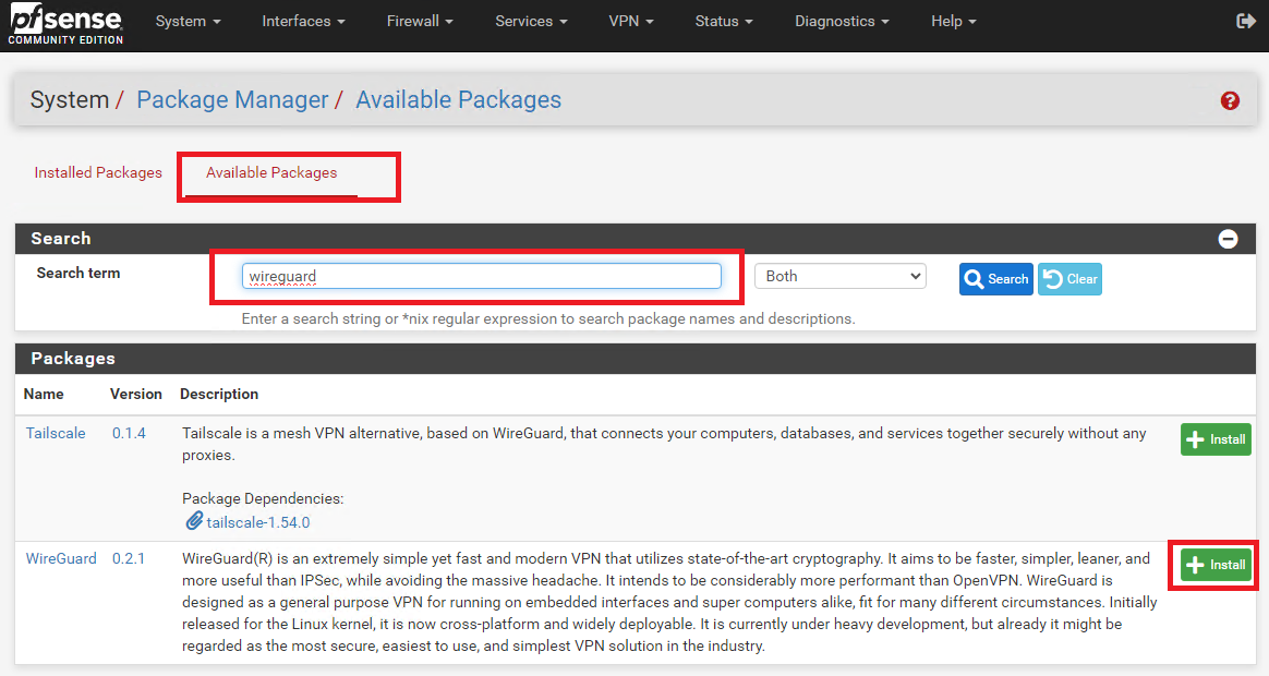
On BOTH site pfsense installations, install the WireGuard package from System ---> Package Manager ---> Available Packages. Enter Wireguard in the Search term field, click search and then click on the Install button next to WireGuard package (Figure 1).
Figure 1
Create Tunnel on Site A
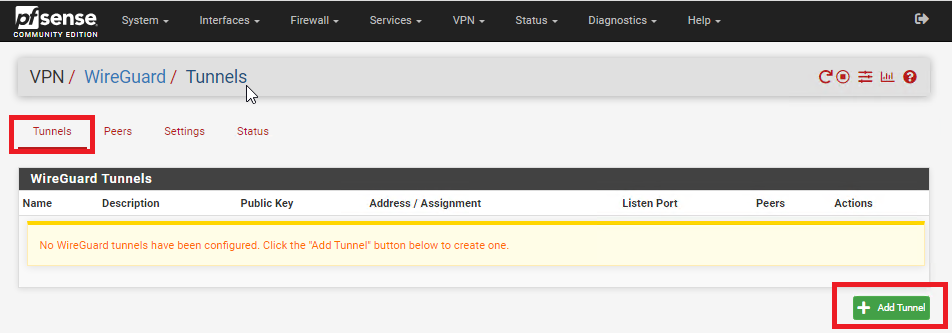
On Site A, refresh the pfsense web GUI and navigate to VPN ---> Wireguard, click on the Tunnels tab and then click on Add Tunnel button (Figure 2).
Figure 2
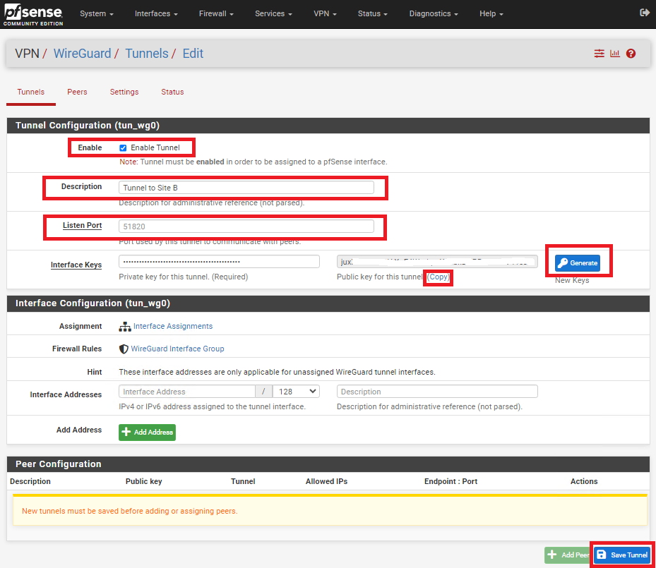
In the Tunnel Configuration fill/set in the following fields (Figure 3):
- Enable: Checked
- Description: Optionally, describe the purpose of this tunnel (Ex: Tunnel to Site B)
- Listen Port: Leave blank to use port UDP/51820 or enter a specific port number you with to use
- Interface Keys: click the Generate button to create a new Private/Public key pair and copy the Public Key that's generated in order to enter it in the Public Key field on Site B.
- Click the Save Tunnel button
Figure 3
Create Tunnel on Site B
On Site B, refresh the pfsense web GUI and navigate to VPN ---> Wireguard, click on the Tunnels tab and then click on Add Tunnel button (Figure 4).
Figure 4
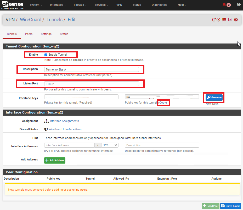
In the Tunnel Configuration fill/set in the following fields (Figure 5):
- Enable: Checked
- Description: Optionally, describe the purpose of this tunnel(Ex: Tunnel to Site A)
- Listen Port: Leave blank to use port UDP/51820 or enter a specific port number you with to use
- Interface Keys: click the Generate button to create a new Private/Public key pair and copy the Public Key that's generated in order to enter it in the Public Key field on Site B.
- Click the Save Tunnel button
Figure 5
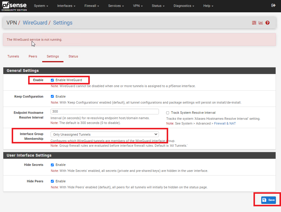
Enable WireGuard on Both Sites
Figure 6
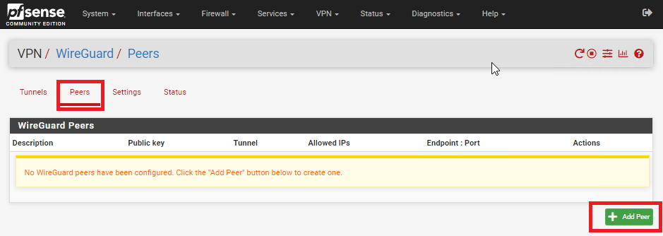
Add Peer on Site A
Figure 7
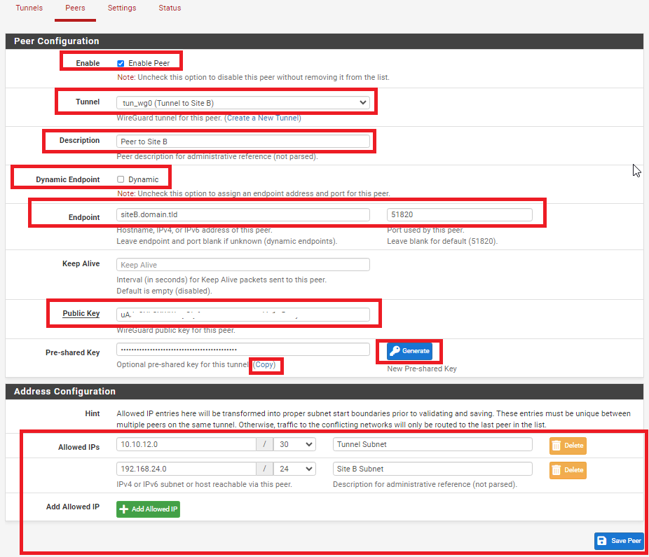
In the Peer Configuration fill/set in the following fields (Figure 8):
- Enable: Checked
- Tunnel: Select the Tunnel previously configured from the drop-down list
- Description: Optionally, describe the purpose of this Peer (Ex: Peer to Site B)
- Dynamic Endpoint: Unchecked
- Endpoint: Fill in the Internet IP or Hostname as well as the port number for Site B
- Public Key: Paste the previously copied Public Key from the Tunnel on Site B
- Pre-shared Key: Click the Generate button to generate a new pre-shared key and copy it in order to paste in the Peer configuration of Site B
- Allowed IPs: Enter an UNUSED Network address (Example: 10.10.12.0) with a CIDR of 30 (For a total of two IPs) in the first field, click the Add Allowed IP and then enter the Network Address and corresponding CIDR of the subnet for Site B
- Click the Save Peer button
Figure 8
Add Peer on Site B
Figure 9
In the Peer Configuration fill/set in the following fields (Figure 10):
- Enable: Checked
- Tunnel: Select the Tunnel previously configured from the drop-down list
- Description: Optionally, describe the purpose of this Peer (Ex: Peer to Site A)
- Dynamic Endpoint: Unchecked
- Endpoint: Fill in the Internet IP or Hostname as well as the port number for Site A
- Public Key: Paste the previously copied Public Key from the Tunnel on Site A
- Pre-shared Key: Paste the previously copied Pre-Shared key from the Peer on Site A
- Allowed IPs: Enter the SAME Tunnel Subnet Network address and CIDR you set on the Peer on Site A, click the Add Allowed IP and then enter the Network Address and corresponding CIDR of the subnet for Site A
- Click the Save Peer button
Figure 10
Configure Interface for Site A
Figure 11
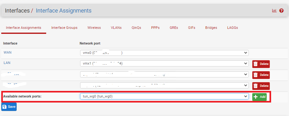
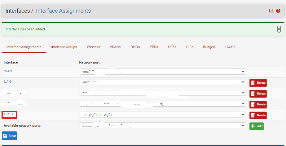
Click on the new OPT(X) interface that was just created (Figure 12).
Figure 12
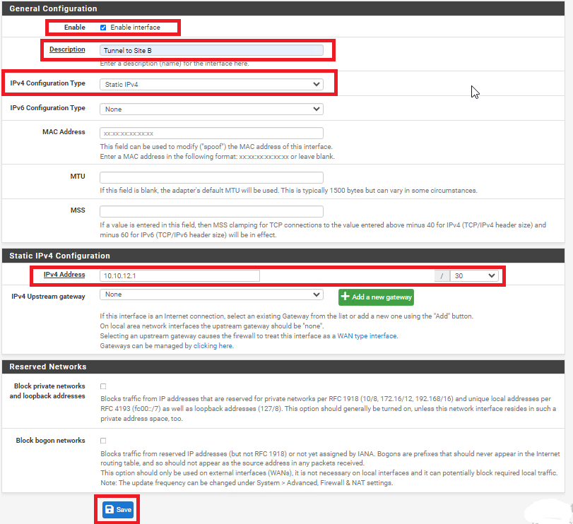
In the General Configuration page fill/set the following fields (Figure 13):
- Enable: Checked
- Description: Optionally, describe the purpose of this Interface (Ex: Tunnel to Site B)
- IPv4 Configuration Type: Static IPv4
- IPv4 Address: Enter an IP address for Site A. The IP address you enter here will be one of two possible IP addresses you can use from the /30 Tunnel Subnet you chose earlier. For this example, we used the Subnet Tunnel of 10.10.12.0/30 which gives us 10.10.12.1 and 10.10.12.2 as the only two usable IPs for this subnet. So, for this example we will use 10.10.12.1 for Site A.
- Click the Save button and then click the Apply Changes button.
Figure 13
Configure Interface for Site B
Figure 14
Click on the new OPT(X) interface that was just created (Figure 15).
Figure 15
In the General Configuration page fill/set the following fields (Figure 16):
- Enable: Checked
- Description: Optionally, describe the purpose of this Interface (Ex: Tunnel to Site A)
- IPv4 Configuration Type: Static IPv4
- IPv4 Address: Enter an IP address for Site B. The IP address you enter here will be one of two possible IP addresses you can use from the /30 Tunnel Subnet you chose earlier. For this example, we used the Subnet Tunnel of 10.10.12.0/30 which gives us 10.10.12.1 and 10.10.12.2 as the only two usable IPs for this subnet. So, for this example we will use 10.10.12.2 for Site B.
- Click the Save button and then click the Apply Changes button.
Figure 16

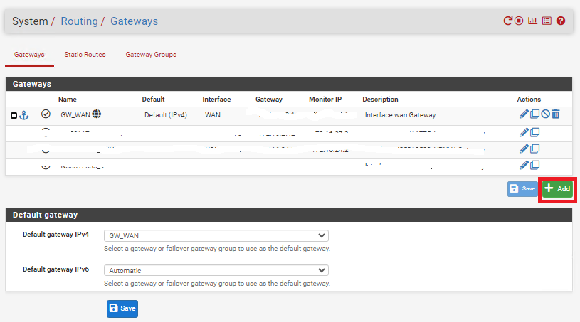
Create Gateway and Route on Site A
Figure 17
In the Edit Gateway page fill/set the following fields (Figure 18):
- Disabled: Unchecked
- Interface: Select the interface for Site A you created earlier
- Name: Enter a name for this gateway (Ex: WG_GW_Site_B)
- Gateway: Enter the Tunnel Subnet IP address for Site B. For this example we used 10.10.12.2 for Site B.
- Description: Optionally, enter a description (Ex: Wireguard Gateway to Site B)
- Click the Save button and then click the Apply Changes button.
Figure 18
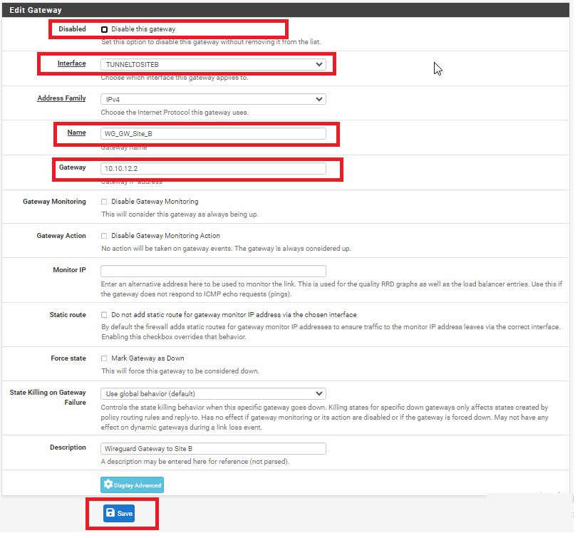
Figure 19
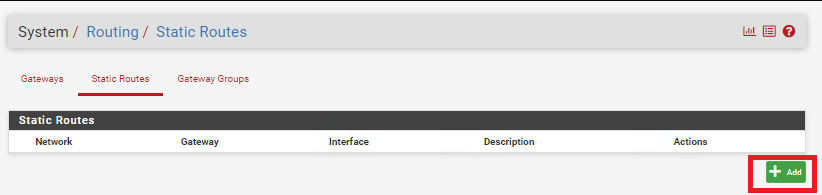
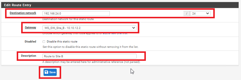
In the Edit Route Entry page, fill/set the following fields (Figure 20):
- Destination network: Enter the network subnet for Site B (NOT the tunnel subnet). In this example, the network subnet we used for Site B was 192.168.24.0/24.
- Gateway: Select the Gateway to Site B you created earlier
- Description: Optionally, enter a description (Ex: Route to Site B)
- Click the Save button and then click the Apply Changes button.
Figure 20
Create Gateway and Route on Site B
Figure 21
In the Edit Gateway page fill/set the following fields (Figure 22):
- Disabled: Unchecked
- Interface: Select the interface for Site A you created earlier
- Name: Enter a name for this gateway (Ex: WG_GW_Site_A)
- Gateway: Enter the Tunnel Subnet IP address for Site A. For this example we used 10.10.12.1 for Site A.
- Description: Optionally, enter a description (Ex: Wireguard Gateway to Site A)
- Click the Save button and then click the Apply Changes button.
Figure 22
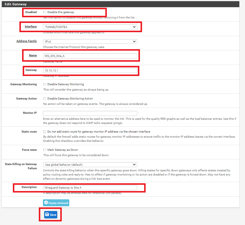
Figure 23
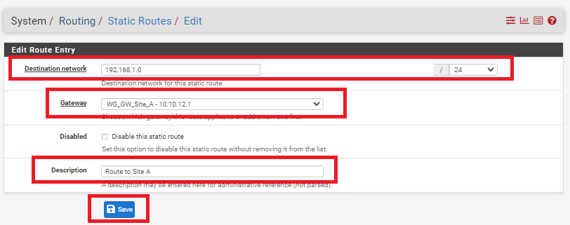
In the Edit Route Entry page, fill/set the following fields (Figure 24):
- Destination network: Enter the network subnet for Site A (NOT the tunnel subnet). In this example, the network subnet we used for Site A was 192.168.1.0/24.
- Gateway: Select the Gateway to Site A you created earlier
- Description: Optionally, enter a description (Ex: Route to Site A)
- Click the Save button and then click the Apply Changes button.
Figure 24
Add Firewall Rules on BOTH Firewalls
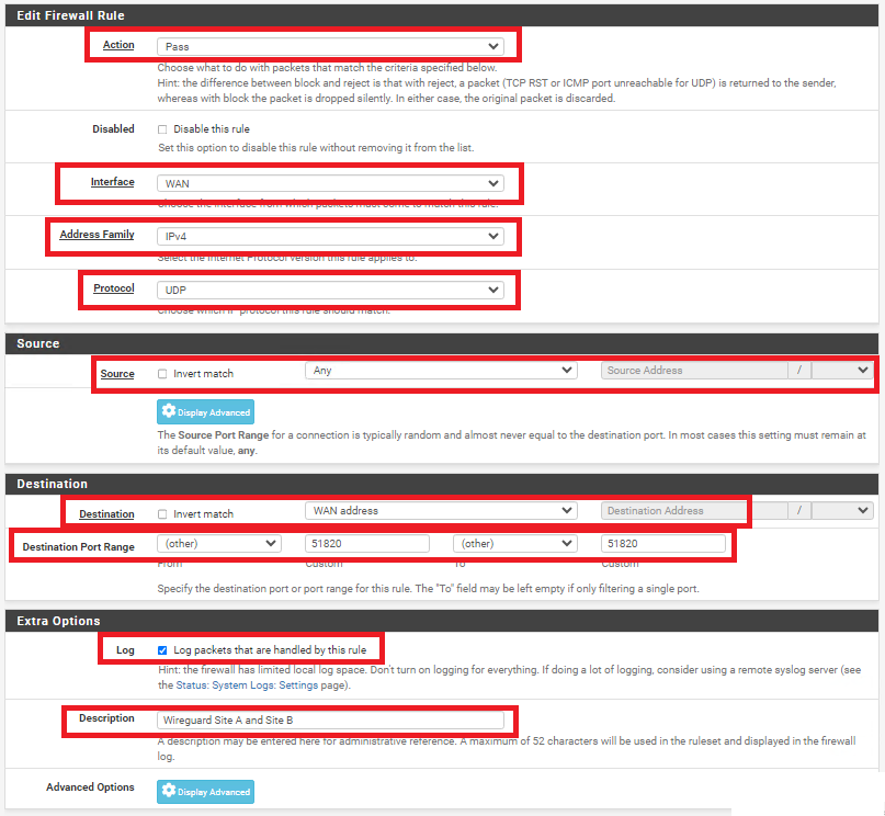
On BOTH firewalls, navigate to Firewall ---> Rules and under the WAN tab, click the Add button. In the Edit Firewall Rule page, fill/set the following fields (Figure 25).
- Action: Pass
- Interface: WAN
- Address Family: IPv4
- Protocol: UDP
- Source: Any
- Destination: WAN address
- Destination Port Range: (other) 51820 to (other) 51820
- Log: Optionally, check to Log packets that are handled by this rule
- Description: Optionally, enter a description (Ex: Wireguard Site A and Site B)
- Click the Save button and then click the Apply Changes button.
Figure 25
On BOTH firewalls, navigate to Firewall ---> Rules and under the TUNNELTOSITE(X) tab, click the Add button. In the Edit Firewall Rule page, fill/set the following fields (Figure 25).
- Action: Pass
- Interface: Ensure the interface you created earlier for each site is already selected
- Address Family: IPv4
- Protocol: Any (Start with Any and then you can tighten the rules further after you ensure tunnel is working properly)
- Source: Any (Start with Any and then you can tighten the rules further after you ensure tunnel is working properly)
- Destination: Any (Start with Any and then you can tighten the rules further after you ensure tunnel is working properly)
- Destination Port Range: Any (Start with Any and then you can tighten the rules further after you ensure tunnel is working properly)
- Log: Optionally, check to Log packets that are handled by this rule
- Description: Optionally, enter a description (Ex: Wireguard Traffic Site A and Site B)
- Click the Save button and then click the Apply Changes button.
Figure 25
Check the Wireguard Status
On BOTH firewalls navigate to Status ---> Wireguard, locate the WireGuard tunnel you created, expand it and ensure the Peers are connected on BOTH firewalls (Figure 26).
Figure 26
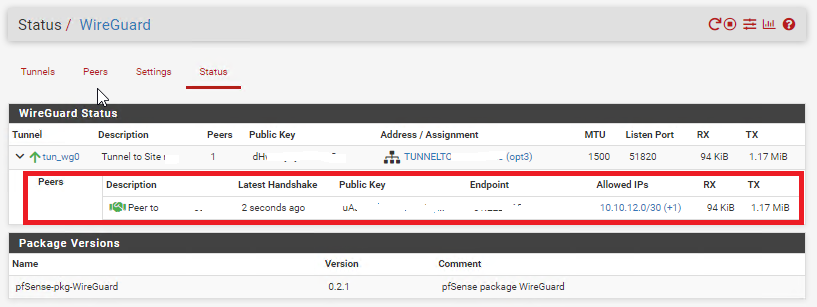
Additionally, ensure you can ping and access resources on each remote network from the corresponding site.